
Article by Jeff Nisley and David Higgins — Photos by Dave Higgins

We have Dave Higgins to thank for spotting the flying potential of a Glider design he noticed in the pages of the November 1979 Issue of Flying Models.
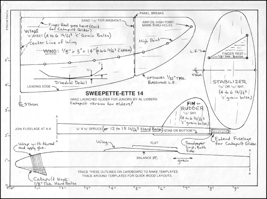
The original glider featured in the magazine article was called the Sweepette-Ette 14.
He brings this glider, designed by Al Lidberg, into the twenty first century by taking the original design, modifying it to his own liking, and with his noteworthy experience—produces a Cad Drawing with the new features that he brings to the table. He also has incorporated a custom DT or De-Thermalizer into his second generation creation that is simple and straight forward. This he details on a separate DT CAD drawing. (A De-Thermalizer is a way to bring down a Model airplane if it gets caught in a thermal.) This same design can be modified to be used with other gliders as well. AMA Glider has an excellent De-Thermalizer Article that explains all about what DTs are, the many types and how they are employed.
Also know that if you have any questions about this article or you just want to leave a comment, please use our LEAVE A REPLY box at the bottom of this page. Also note that others can respond to your comment which would effectively start a discussion—which would be a good thing.
So just to be clear—what we want to point out here is that we are showcasing the second version of the Sweepette-Ette 14 which is the Sweepette-Ette 14 Mk. II.
Mark II or Mark 2 often refers to the second version of a product, frequently military hardware.
“Mark”, meaning “model” or “variant”, can be abbreviated “Mk.”
But wait—Dave realizes that there is value in the original article put out in 1979 by Flying models that has step-by-step instructions on how to make this glider. In Dave’s words, “The original magazine article does a good job of explaining how to go about building the glider using simple tools and techniques.”
Later on in this article we will make a copy of the original article available for you to download as pdf files, but first I would like to have Dave explain in his own words how this project came about.
In my humble opinion, it’s an interesting heroic saga—and quite an achievement. But first I would like to put out a spoiler alert telling you in advance about the success of his new glider and the terrific results of his efforts:
“BTW, yesterday I launched this glider at the ERMA RC field twice,
Quote from Dave Higgins in an email to Jeff Renz and Jeff Nisley — Sunday August 23rd, 2020
and both times I snagged a thermal and the D.T. kept the glider from flying away!
David Higgins writes:
Several months ago I found an old article from Flying Models magazine (November 1979 issue) on Al Lidberg’s Sweepette-Ette 14 hand launched glider, and I marked up the plan for this glider to make a catapult version of it and then sent the PDF file for the magazine article and marked up plan to several model airplane friends, including Jeff Renz. I forgot all about this glider until Jeff emailed me a couple of weeks ago asking me if he could put the article and plan on the HAFFA website. I told him to go ahead, then I immediately decided to build one to see how well it would fly.

Pages 1 & 2 of the Sweepette – Ette 14 article from the November 1979
issue of Flying Models — Printable PDF files
Pages 3 & 4 of the Sweepette – Ette 14 article from the November 1979
issue of Flying Models — Printable PDF files
In the process of building it, I made a few minor changes and incorporated those changes into a CAD drawing and named this new glider the Sweepette-Ette 14 Mk. II to indicate a revision to the original glider design. The main differences between the Mk. II version and the marked up magazine plan version are the shape of the stabilizer, the addition of a hand hold at the very aft end of the fuselage, a slight change in the airfoil shape, the additions of a wash-in wedge and bass wood leading edge, and a ½” increase in the wing span. Although these changes were not absolutely necessary, they do help improve the performance of the glider.
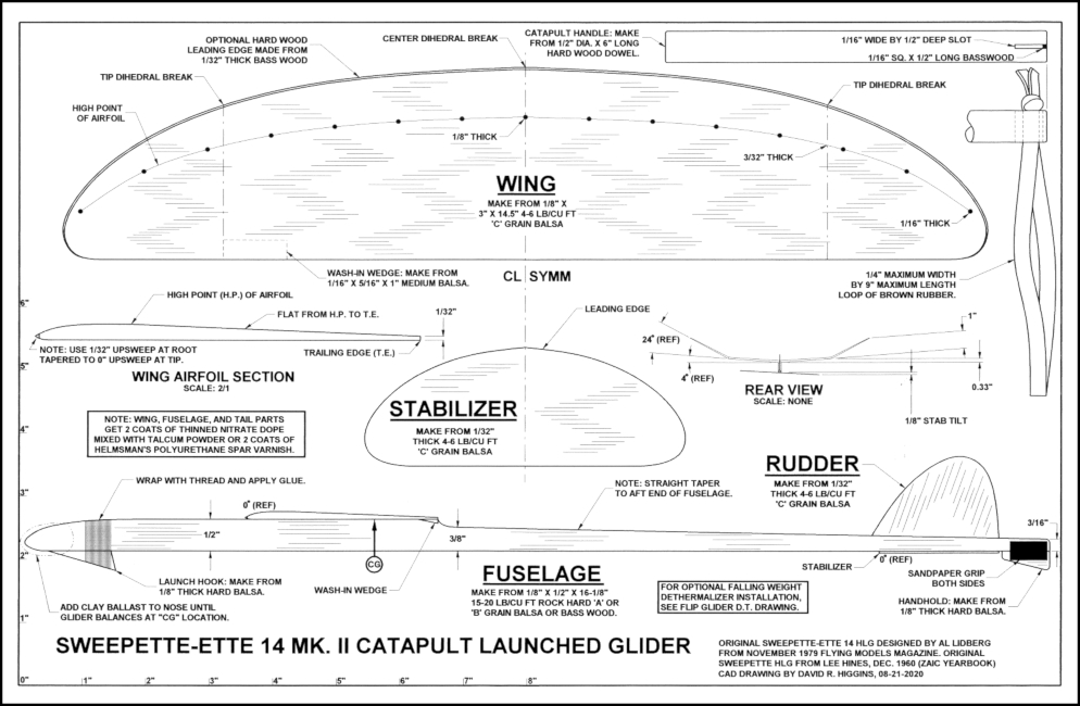
Shown at left is the CAD Drawing of the Sweepette-Ette 14 Mk. II Catapult Launched Glider
To download this PDF file of the drawing, click on the Download Button.

The drawing’s full size is 11″ x 17″. If this is too large for your printer, you can copy the file to a USB flash drive and take it to an Office Print & Ship Center like FedEx or Staples and they will be able to print it for you at full scale, which is what you want.
At the right is Dave’s CAD drawing of the DT system he calls the FLIP D. T. SYSTEM which he designed for the Sweepette-Ette 14 Mk. II.
It can however be adopted for use on other similar sized Catapult Launched Gliders as well.
To download this PDF file of the drawing, click on the Download Button.

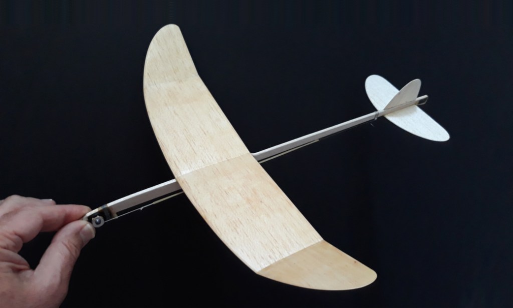

Here is a Slide Show featuring the
Sweepette-Ette 14 Mk. II Catapult Launched Glider with Dave’s effective DT System.
Notice that you can compare version two with the original marked up copy from the article by using the left and right arrows. I can see now why he chose to better the stab shape. Also note that on the Mk. II drawing, Dave gives you detailed instructions on how to make the catapult handle and 9″ loop of 1/4″ brown rubber. I’m fairly certain that the specs on this have been thoroughly researched through trial and error for optimum results.
Again thanks for bringing to us all the means to build a very fine looking and FLYING I might add— CATAPULT LAUNCHED GLIDER!!!
Dave Higgins is a new contributor and Jeff Nisley has been a regular contributor to our KC Free Flight website.
If you have any questions or comments about this page or gliders in general, be sure to LEAVE A REPLY below.


Clarification on the Sweepette-Ette 14 Mk. II: I forgot to mention on the plan to sand a 1/8″ wide flat on the lower surface of the wing along the center dihedral joint where it interfaces with the fuselage, otherwise you will have tapered gaps between the wing and the fuselage. Also, it is a good idea to add generous glue fillets on both sides of the wing/fuselage joint, otherwise the wing might depart the fuselage during the launch phase.
Clarification on the Flip D.T. System: You will need to drill a small (0.020″ – 0.025″) diameter hole through the 0.18″/0.20″ diameter lead shot “bead” to attach the nylon string to it. The lead shot “bead” holds the nylon string in the tapered slot of the D.T. arm as shown in the first photo of the Sweepette-Ette 14 Mk. II. When the D.T. arm rotates down far enough, the string slips out of the tapered slot in the D.T. arm allowing the bead to fall aft, causing the center of gravity to shift aft, which causes the glider to whip stall and fall out of a thermal.