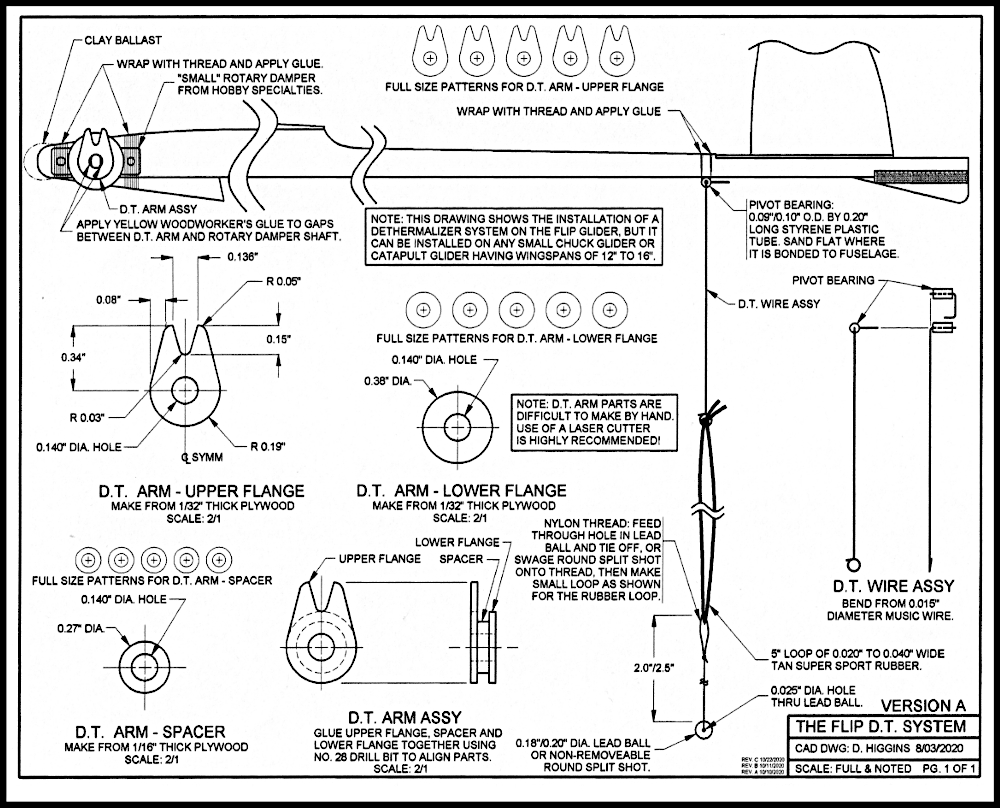
The Flip Dethermalizer System for 12” to 16” Wingspan Gliders.
There are two very similar versions of this simple falling weight dethermalizer (D.T.) system. Version A has a built-up plywood D.T. arm that requires either a high degree of skill to build or a laser cutter capable of cutting 1/32” thick plywood. Version B has a built-up styrene plastic D.T. arm that requires less skill to build than Version A. The photos below show the version A plywood D.T. arm.


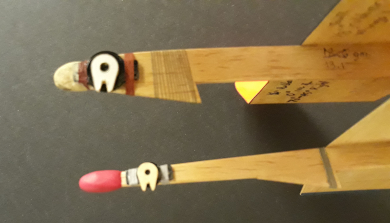
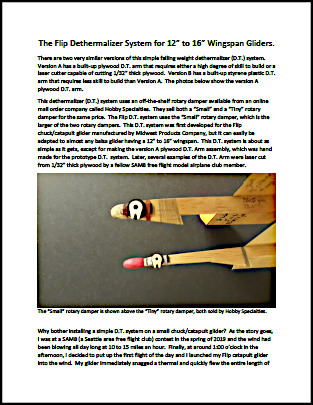
The “Small” rotary damper is shown above the “Tiny” rotary damper, both sold by Hobby Specialties.
This dethermalizer (D.T.) system uses an off-the-shelf rotary damper available from an online mail order company called Hobby Specialties. They sell both a “Small” and a “Tiny” rotary damper for the same price. The Flip D.T. system uses the “Small” rotary damper, which is the larger of the two rotary dampers. This D.T. system was first developed for the Flip chuck/catapult glider manufactured by Midwest Products Company, but it can easily be adapted to almost any balsa glider having a 12” to 16” wingspan. This D.T. system is about as simple as it gets, except for making the version A plywood D.T. Arm assembly, which was hand made for the prototype D.T. system. Later, several examples of the D.T. Arm were laser cut from 1/32” thick plywood by a fellow SAM8 free flight model airplane club member.
Why bother installing a simple D.T. system on a small chuck/catapult glider?
As the story goes, I was at a SAM8 (a Seattle area free flight club) contest in the spring of 2019 and the wind had been blowing all day long at 10 to 15 miles an hour. Finally, at around 1:00 o’clock in the afternoon, I decided to put up the first flight of the day and I launched my Flip catapult glider into the wind. My glider immediately snagged a thermal and quickly flew the entire length of the field. Fortunately, it came out of the thermal and landed in a small tree at the far end of the field. I shook the tree and got the glider to fall to the ground and immediately started thinking about a simple D.T. system for small gliders.
I have a binder full of old chuck/catapult glider plans and on one of these drawings I came across a simple falling weight D.T. system that uses a burning fuse. I simply substituted a rotary damper for the burning fuse and a lead shot ball (or a round split shot used in fishing) for the plastic bead that interfaces with the slot in the D.T. arm. The lead shot ball weighs between 0.6 grams and 1 gram depending on its diameter. When the lead ball falls away from the slot in the D.T. arm, it falls down and aft causing the center of gravity of the glider to shift aft about 0.75 inches, which causes the glider to suddenly stop circling in the thermal and immediately whip stall. To date, I’ve had at least a dozen successful D.T.s with this system in light thermal conditions. I honestly don’t know how well this system will work in heavy thermal conditions found in the Southwest and Midwest regions of the U.S.
Download the Instructions to the
Flip Dethermalizer System for for 12” to 16” Wingspan Gliders.
The same text you see on this web page is available
as a downloadable pdf document for printing purposes here.

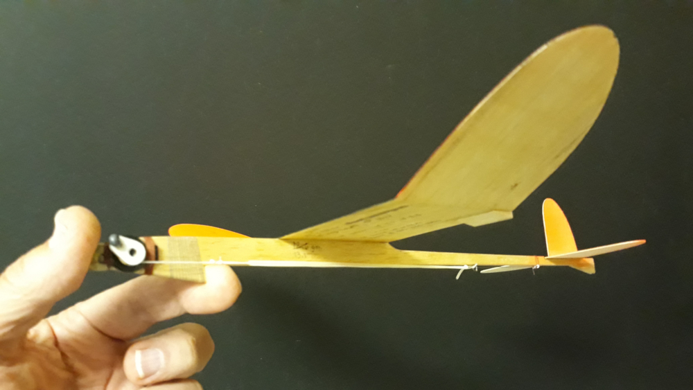
Rotary damper with D.T. arm mounted to glider with thread and glue. Note the lead ball “bead.”
Building and Installing the Flip D.T. system:
- Build the D.T. Arm Assembly, which consists of the upper flange (the actual timer arm with the “V” slot), a spacer and a lower flange. See the Flip D.T. System drawing (version A or version B) for the detail part dimensions. If you are building the version A plywood D.T. arm, you will save a lot of time and frustration If you know someone with a laser cutter willing to cut these parts for you. I built the prototype version A plywood D.T. arm using tiny homemade brass hole saw cutters, a drill press, a precision disk sander a Dremel rotary tool and a number 28 drill bit. Fortunately, I was able to get a fellow SAM8 club member to cut the D.T. arm parts out on his professional grade laser cutter; the parts came out perfect and saved me a bunch of time. He cut everything from 1/32” thick plywood, so he made two 1/32” thick spacers instead of the one 1/16” thick spacer called out on the plan. Make sure to orient the long direction of the upper flange (the 1/32” thick part having the “V” slot) parallel with the grain of the exterior plies of the plywood. Use a number 28 drill bit shank to assemble the D.T. Arm parts. I used yellow wood worker’s glue to assemble the D.T. Arm parts. Make sure to use a toothpick to wipe off the excess glue that oozes out of the spacer/flange joints. After drying for a couple minutes, carefully slip the D.T. Arm Assembly off the drill bit shank using a 1 inch length of 3/32” O.D. brass tubing. Don’t wait too long or the D.T. Arm will be difficult if not impossible to remove from the drill bit shank. I recommend finishing the Version A plywood D.T. Arm Assembly with two coats of thinned nitrate dope or a coat of Minwax Helmsman Spar Urethane varnish. The version B styrene plastic D.T. arm is a much simpler design, requiring less time and skill to build. Although not absolutely necessary, the square corners on the plastic D.T. arm parts can be rounded to make them more professional looking. The plastic D.T. arm parts are glued together on the shank of a 1/8” diameter drill bit using Testors liquid cement for plastics. Once the glue has been applied to the plastic D.T. arm parts and they have been aligned on the drill bit shank, quickly remove the D.T. arm assembly from the shank to prevent it from bonding permanently to the shank. A small rat-tail file is used to gradually increase the hole in the D.T. arm assembly until it fits snugly onto the output shaft common to the rotary damper.
2. When fully dry, press the D.T. arm assembly (whichever version you built) onto the rotary damper and apply yellow woodworker’s glue to the gaps as shown on the Flip D.T. System drawing. Use Duco cement or Super Glue Gel to attach the rotary damper to the nose of the glider, then wrap thread around the rotary damper’s mounting tabs and fuselage and apply glue.
3. Make the D.T. Wire Assembly next, which uses a 0.20” long by 0.10” O.D. styrene plastic pivot bearing and 0.015” diameter music wire. Why not simply use a piece of nylon thread tied to a sewing pin attached to the fuselage located near the aft end of the glider instead of a piece of wire that rotates? The D.T. Wire Assembly has a built-in stop that keeps the wire from rotating beyond 90 degrees from its original position, which helps to prevent the D.T. lead ball from hitting or wrapping around the somewhat fragile stabilizer. Using round nose pliers (available from Wal-Mart or Michael’s craft stores) bend a small circular loop on one end of a 5” to 6” long piece of 0.015” diameter music wire. Next, bend the wire 90 degrees approximately 2.5” to 2.7” from the circular loop and place the pivot bearing on the wire and bend the wire 90 degrees by hand to capture the pivot bearing, making sure to orient the wire according to the drawing. Lastly, make one more 90 degree bend about 1/4” from the center of the pivot bearing and cut off the excess wire such that about 1/8” to 3/16” of the wire extends beyond the last bend.
4. Sand/file a small flat on the pivot bearing, then glue the pivot bearing (common to the D.T. Wire Assembly) to the fuselage at the location shown on the drawing using Duco cement or Super Glue gel and allow to dry thoroughly. Next, wrap thread around the fuselage and pivot bearing and apply glue, being careful not to get glue in the pivot bearing.
5. Obtain a lead ball of 0.18”/0.20” diameter and gently tap it on a flat metal surface with a hammer to make a small diameter flat area. Drill a 0.025” diameter hole all the way through the lead ball by hand using a pin vise. Thread a 6” length of nylon thread through the hole in the lead ball, tie it securely to the ball and apply Duco cement to the knot. Alternatively, you can swage a small round non-removeable split shot (normally used on fishing line) to one end of the nylon thread. Now make a small loop about 2” to 2.5” from the lead ball (or the split shot) as shown on the Flip D.T. System drawing and apply Duco cement to the knot.
6. This next step requires a rubber stripper. If you don’t have one, borrow one from an indoor free flight enthusiast, or you can order Super Sport rubber custom stripped to any width desired from Freedom Flight Models: http://freedomflightmodels.com/rubber.php Make or purchase a 0.020” to 0.040” wide strip of Tan Super Sport rubber approximately 20 feet long. Take a 12” length of this stripped rubber and thread it through the nylon thread loop common to the lead ball (or swaged round split shot) and then through the circular loop in the D.T. wire assembly. Tie an overhand knot in the rubber strip to retain it as shown on the drawing. A fellow club member tried using the small tension spring sold by Hobby Specialties instead of the thinly stripped Tan Super Sport rubber, but he had difficulty adjusting the spring tension to increase/decrease the D.T. pop-off times, so he finally gave up and went back to the thinly stripped rubber. This finishes the D.T. system installation.

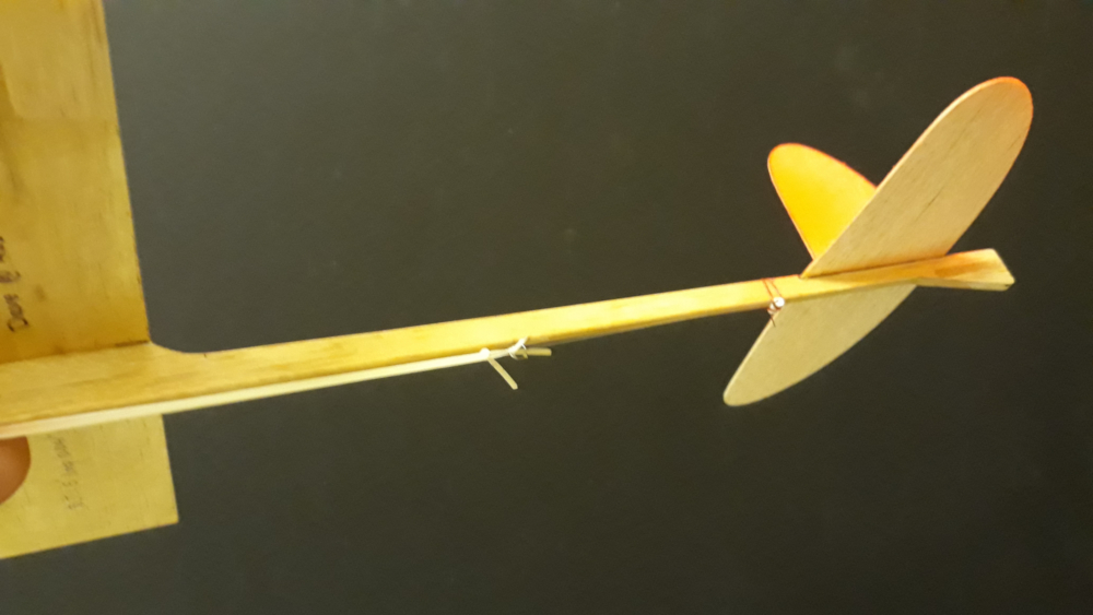
Pivot bearing mounted to lower surface of fuselage just forward of the stabilizer using thread and glue.

The completed Flip D.T. system armed and ready for a short D.T. flight.
7. To speed up the D.T. system for shorter D.T. flight times, shorten the overall length of the rubber loop by pulling on the loose ends of the rubber loop. Lengthening the rubber loop will lengthen the D.T. time. To prevent the lead ball (or the swaged round split shot) from being ejected from the slot in the D.T. arm assembly during the high speed catapult launch, make sure that the nylon thread is wrapped at least 360 degrees (1 revolution) around the spacer common to the D.T. arm assembly. If you are flying on a fairly small field and therefore require a short D.T. time, shorten the rubber loop as required such that the lead ball/split shot rotates 360 degrees (1 revolution) and falls after only 30 seconds. When launching with a fast moving D.T., make sure you have 540 degrees (1-1/2 a revolutions) of rotation before the lead ball/split shot falls out of the D.T. arm assembly, to give yourself extra time to set the catapult rubber onto the glider’s hook and to aim the glider before letting go of the glider. Oh, and by the way, you will see your model much better after it lands if you paint the upper surfaces of the wing tips and both sides of the rudder with Krylon fluorescent orange. Happy Flying!
The Flip DT System Gallery and Slide Show
 Click any photo to go to a Slide Show. Use the Esc key (top left corner) on your keyboard to exit the Slide Show,
or click on any black area around any photo to also exit.