
February 2017 Project of the Month — By Jeff Nisley
This project is second in a series of projects meant to aid model aircrafters.
Pictured above is a closeup of two Stuffer Stick ends. The one nearest one to us was made some time ago by Mike Basta and was the inspiration I used to make the more simpler one shown in the background. To be quite honest I like the looks of Mike’s better but it looked harder to make so I decided to simplify mine somewhat. My design is simply to glue two fork pieces made out of thin plywood to a dowel rod, the length of your choosing. The plywood thickness was 1/16″ thick plywood for a 5/16″ dowel rod, and it ended up 24″ long based on my needs.
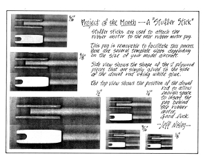 At right is a PDF Document that has patterns for different sized Stuffer Sticks based on dowel rod sizes of 1/8″ (peanut scale), 3/16″, 1/4″, 5/16″, 3/8″, and for really big models, I have one for a whopping 1/2″ dowel rod.
Click this link: STUFFER STICK PDF to download and print a copy to make your own stuffer stick.
For those of us new to the hobby (like the author was last summer) I will try to explain what a stuffer stick is and how it is used by using photos:

Stuffer Sticks are used to attach the rubber motor to the rear Rubber motor peg.
If you look closely at the model aircraft above sitting on a stooge, there is a pin that is holding up the rear of the aircraft. This pin goes through the rear motor “peg”. This peg can be made of wood but in this case it is a hollow shaft of aluminum tubing.
To attach the rubber motor to this rear motor peg inside the fuselage, a stuffer stick is used by taking off the nose piece and inserting it down the fuselage (inside a blast tube). The stuffer stick can be of any length but must be longer than the distance from the peg to the nose.
 My design is simplified to just have two fork pieces glued to the side of a dowel rod. You can use white glue or carpenters wood glue.
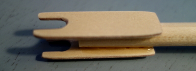
I started with just a small amount of glue, lined up visually the two forks and let it dry overnight. Then I added more. By progressively adding more and more glue to the joint after each layer dries, it becomes a very strong bond. I have added more since these photos were taken just for good measure. Be sure to round the ends of the plywood as they are going in and out of your model aircraft’s fuselage so it won’t tear up the sticks inside.
Notice the position of the dowel rod to the right of the round portion of the forks. This is the space that allows the peg to be inserted through the fuselage, and should be about at least 1-1/2 times the diameter of the pin. (See below.)
 This photo shows the end of the stuffer stick bringing the rubber motor to the area of the rear motor Peg.
Note that the open bay on the aircraft shown at left is on the bottom of the model where you have access.
This photo also shows that the motor peg has been pulled out of one of the sides.
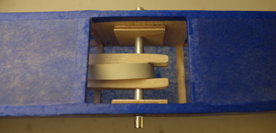 This 2nd photo shows the rubber motor being placed behind the peg and the peg having been pushed through to the other side of the fuselage where it is now centered on the fuselage.
 Finally the stuffer stick is retracted out of the nose of the aircraft leaving the rubber motor on the peg.
This isn’t rocket science stuff but there was a time not so far in the past that I had no clue as to how this was all done. Once you see it—it all makes sense.
I mentioned Blast tubes earlier. Next time I will pick up that subject and show you how to make them more effective from a tip I happened to find.
Jeff Nisley is an editor of the website Flyhaffa.com and would like to hear from you if you have any comments or suggestions at jeffnisley@ymail.com. Thanks
